Generally Conforms to, DIN VDE 0282 PART 810, IEC 245, BS7655,BS7919/ HD22.1, HD22.4
| Conductor | : | Flexible Class 5 copper conductor according to DIN VDE 0295,IEC 60228 |
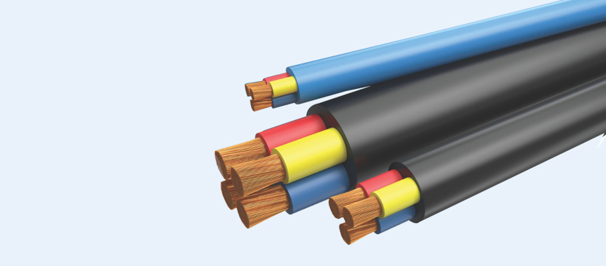
| Insulation | : | EPDM-rubber, core identification by colours |
| Sheathing | : | Weather - and oil resistant rubber Black or Blue, |
*Any other Color on specific request can also be supplied
| Operating Temp | : | -25°c to max.+90°C |
| Nominal voltage | : | 450/750 V |
| Test voltage | : | 2500 V |
| Min. bending radius | : | 8 x cable diameter |
| Flame propagation | : | Flame retardant test as per IEC 60332-1 |
HO7RN-F
Yogicab H07RN-F rubber insulated and sheathed cables are intended for flexible connection to electrical equipment. They are suitable for both indoor and outdoor use in industrial and agricultural plant and on construction sites.
Standard length cable packing:
Coils 100 and 200 m in carton boxes, reels
| Sq. mm | Nos/ dia. (Nom.) | Insulation
Thicknes in mm ( nom.) |
Core dia. In mm | Sheath Thickness in mm (nom.) |
Cable dia. In mm (Nom.) |
Max. C.R in ohm/km Copper |
| 1 C X 1.5 | 22/0.300 | 0.80 | 3.25 | 1.40 | 6.20 | 12.10 |
| 1 C X 2.5 | 36/0.300 | 0.80 | 3.80 | 1.40 | 6.70 | 7.41 |
| 1 C X 4 | 56/0.300 | 0.90 | 4.50 | 1.50 | 7.50 | 4.95 |
| 1 C X 6 | 84/0.300 | 1.00 | 5.25 | 1.60 | 8.60 | 3.30 |
| 1 C X 10 | 140/0.300 | 1.00 | 7.00 | 1.80 | 10.80 | 1.91 |
| 1 C X 16 | 224/0.300 | 1.20 | 8.15 | 1.90 | 12.20 | 1.21 |
| 1 C X 25 | 350/0.300 | 1.20 | 9.95 | 2.00 | 14.20 | 0.780 |
| 1 C X 35 | 490/0.300 | 1.40 | 11.10 | 2.20 | 15.70 | 0.554 |
| 1 C X 50 | 703/0.300 | 1.40 | 13.30 | 2.40 | 18.30 | 0.386 |
| 1 C X 70 | 988/0.300 | 1.60 | 15.15 | 2.60 | 20.60 | 0.272 |
| 1 C X 95 | 1349/0.300 | 1.60 | 17.55 | 2.80 | 23.40 | 0.206 |
| 1 C X 120 | 608/0.500 | 1.80 | 19.45 | 3.00 | 25.70 | 0.161 |
| 1 C X 150 | 760/0.500 | 2.00 | 21.30 | 3.20 | 27.90 | 0.129 |
| 1 C X 185 | 943/0.500 | 2.20 | 23.90 | 3.40 | 30.80 | 0.106 |
| 1 C X 240 | 1225/0.500 | 2.40 | 27.10 | 3.50 | 34.10 | 0.0801 |
| 1 C X 300 | 1498/0.500 | 2.60 | 29.60 | 3.60 | 36.80 | 0.0641 |
| 1 C X 400 | 2035/0.500 | 2.80 | 33.80 | 3.80 | 41.60 | 0.0486 |
The number of wires is approximate and wire diameter is nominal; they shall be such as to satisfy the requirements of conductor resistance of IEC 60228 / DIN VDE 0295 / IS 8130 / BS 6360 or UL83
| Sq. mm | Nos/ dia. (Nom.) | Insulation
Thicknes in mm ( nom.) |
Core dia. In mm | Sheath Thickness in mm (nom.) |
Cable dia. In mm (Nom.) |
Max. C.R in ohm/km Copper |
| 2 C X 1 | 14/0.300 | 0.80 | 3.00 | 1.30 | 8.70 | 18.1 |
| 2 C X 1.5 | 22/0.300 | 0.80 | 3.25 | 1.50 | 9.60 | 12.10 |
| 2 C X 2.5 | 36/0.300 | 0.90 | 3.80 | 1.70 | 11.10 | 7.41 |
| 2 C X 4 | 56/0.300 | 1.00 | 4.50 | 1.80 | 12.90 | 4.95 |
| 2 C X 6 | 84/0.300 | 1.00 | 5.25 | 2.00 | 14.70 | 3.30 |
| 2 C X 10 | 140/0.300 | 1.20 | 6.50 | 3.10 | 19.40 | 1.91 |
| 2 C X 16 | 224/0.300 | 1.20 | 8.00 | 3.30 | 22.70 | 1.21 |
| 2 C X 25 | 350/0.300 | 1.40 | 10.10 | 3.60 | 27.50 | 0.780 |
The number of wires is approximate and wire diameter is nominal; they shall be such as to satisfy the requirements of conductor resistance of IEC 60228 / DIN VDE 0295 / IS 8130 / BS 6360 or UL83
| Sq. mm | Nos/ dia. (Nom.) | Insulation
Thicknes in mm ( nom.) |
Core dia. In mm | Sheath Thickness in mm (nom.) |
Cable dia. In mm (Nom.) |
Max. C.R in ohm/km Copper |
| 3 C X 1 | 14/0.300 | 0.80 | 3 | 1.4 | 9.45 | |
| 3 C X 1.5 | 22/0.300 | 0.80 | 3.25 | 1.6 | 10.20 | 12.10 |
| 3 C X 2.5 | 36/0.300 | 0.90 | 3.80 | 1.8 | 11.90 | 7.41 |
| 3 C X 4 | 56/0.300 | 1.00 | 4.50 | 1.90 | 13.50 | 4.95 |
| 3 C X 6 | 84/0.300 | 1.00 | 5.25 | 2.10 | 15.60 | 3.30 |
| 3 C X 10 | 140/0.300 | 1.20 | 6.50 | 3.30 | 20.60 | 1.91 |
| 3 C X 16 | 224/0.300 | 1.20 | 8.00 | 3.50 | 24.20 | 1.21 |
| 3 C X 25 | 350/0.300 | 1.40 | 10.10 | 3.80 | 29.10 | 0.780 |
| 3 C X 35 | 490/0.300 | 1.40 | 11.30 | 4.10 | 32.10 | 0.554 |
| 3 C X 50 | 703/0.300 | 1.60 | 13.30 | 4.50 | 38.10 | 0.386 |
| 3 C X 70 | 988/0.300 | 1.60 | 15.30 | 4.80 | 42.30 | 0.272 |
| 3 C X 95 | 1349/0.300 | 1.80 | 18.00 | 5.30 | 49.10 | 0.206 |
| 3 C X 120 | 608/0.500 | 2.00 | 19.80 | 5.90 | 54.60 | 0.161 |
| 3 C X 150 | 760/0.500 | 2.20 | 22.00 | 6.00 | 59.50 | 0.129 |
| 3 C X 185 | 943/0.500 | 2.400 | 23.70 | 6.50 | 64.30 | 0.106 |
The number of wires is approximate and wire diameter is nominal; they shall be such as to satisfy the requirements of conductor resistance of IEC 60228 / DIN VDE 0295 / IS 8130 / BS 6360 or UL83
| Sq. mm | Nos/ dia. (Nom.) | Insulation
Thicknes in mm ( nom.) |
Core dia. In mm | Sheath Thickness in mm (nom.) |
Cable dia. In mm (Nom.) |
Max. C.R in ohm/km Copper |
| 4 C X 1 | 14/0.300 | 0.80 | 3.00 | 1.5 | 10.7 | 18.1 |
| 4 C X 1.5 | 22/0.300 | 0.80 | 3.25 | 1.70 | 11.2 | 12.10 |
| 4 C X 2.5 | 36/0.300 | 0.90 | 3.80 | 1.90 | 13 7.41 | |
| 4 C X 4 | 56/0.300 | 1.00 | 4.50 | 2.00 | 14.9 | 4.95 |
| 4 C X 6 | 84/0.300 | 1.00 | 5.25 | 2.30 | 17.5 | 3.30 |
| 4 C X 10 | 140/0.300 | 1.20 | 6.50 | 3.40 | 22.6 | 1.91 |
| 4 C X 16 | 224/0.300 | 1.20 | 8.00 | 3.60 | 27.1 | 1.21 |
| 4 C X 25 | 350/0.300 | 1.40 | 10.10 | 4.10 | 32.7 | 0.780 |
| 4 C X 35 | 490/0.300 | 1.40 | 11.30 | 4.40 | 36.2 | 0.554 |
| 4 C X 50 | 703/0.300 | 1.60 | 13.30 | 4.80 | 42.3 | 0.386 |
| 4 C X 70 | 988/0.300 | 1.60 | 15.30 | 5.20 | 48.2 | 0.272 |
| 4 C X 95 | 1349/0.300 | 1.80 | 18.00 | 5.90 | 55.6 | 0.206 |
| 4 C X 120 | 608/0.500 | 2.00 | 19.80 | 6.00 | 61.2 | 0.161 |
| 4 C X 150 | 760/0.500 | 2.20 | 22.00 | 6.50 | 66.00 | 0.129 |
| 4C X 185 | 943/0.500 | 2.40 | 23.70 | 6.90 | 71.5 | 0.106 |
The number of wires is approximate and wire diameter is nominal; they shall be such as to satisfy the requirements of conductor resistance of IEC 60228 / DIN VDE 0295 / IS 8130 / BS 6360 or UL83
| Sq. mm | Nos/ dia. (Nom.) | Insulation
Thicknes in mm ( nom.) |
Core dia. In mm | Sheath Thickness in mm (nom.) |
Cable dia. In mm (Nom.) |
Max. C.R in ohm/km Copper |
| 5 C X 1 | 14/0.300 | 0.80 | 3.00 | 1.60 | 11.50 | 18.1 |
| 5 C X 1.5 | 22/0.300 | 0.80 | 3.25 | 1.80 | 12.60 | 12.10 |
| 5 C X 2.5 | 36/0.300 | 0.90 | 3.80 | 2.00 | 14.50 | 7.41 |
| 5 C X 4 | 56/0.300 | 1.00 | 4.50 | 2.20 | 16.80 | 4.95 |
| 5 C X 6 | 84/0.300 | 1.00 | 5.25 | 2.50 | 19.40 | 3.30 |
| 5 C X 10 | 140/0.300 | 1.20 | 6.50 | 3.60 | 25.10 | 1.91 |
| 5 C X 16 | 224/0.300 | 1.20 | 8.00 | 3.90 | 29.70 | 1.21 |
| 5 C X 25 | 350/0.300 | 1.40 | 10.10 | 4.40 | 36.40 | 0.780 |
| 5 C X 35 | 490/0.300 | 1.40 | 11.30 | 4.60 | 40.00 | 0.554 |
The number of wires is approximate and wire diameter is nominal; they shall be such as to satisfy the requirements of conductor resistance of IEC 60228 / DIN VDE 0295 / IS 8130 / BS 6360 or UL83
![]()
